
Open Shortest Path First (OSPF)
It is a link state routing protocol that was developed as an alternative for the distance vector Routing Information Protocol (RIP). RIP reliance on hop count as the only metric for determining best route had some challenges.
Using hop count doesn’t work well in larger networks with multiple paths and varying speeds.
OSPF has faster convergence and scales to much larger network implementations.
- It is a widely used and supported routing protocol
- It is an open standard meaning almost all routers supports it
- It is an interior gateway protocol meaning it is designed to be used by a single autonomous system.
- Consists of single area and multi area OSPF
- OSPFv2 is used for IPv4 networks
- OSPFv3 is used for IPv6 networks
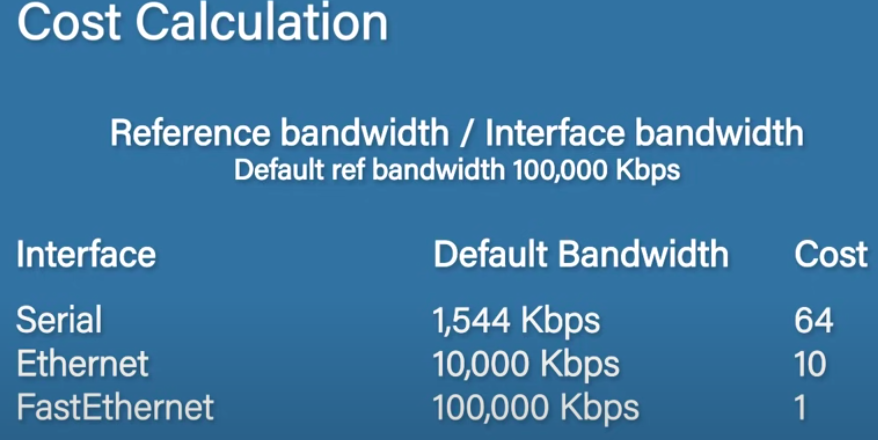
Neighbor Adjacencies are first established by the routers. OSPF floods link state information to all neighboring routers using Link State Advertisements(LSAs). Each router then takes those LSAs and builds a Link State Database (LSDB). They then run the SPF algorithm which calculates cost of routes. Finally, routers choose the best routes based on the route cost.
Router ID Selection
Each router needs to choose a router ID. It is used to identify an individual router and has an IPv4 address.
- The router first checks if the router ID has been manually assigned.
- If not, the router will choose the highest up loopback ip address.
- If not, it will choose the highest non-loopback ip address.
OSPF Operational States
1. Down state
- When ospf is enabled on an interface, the router must determine if there is another OSPF neigbor on the link.
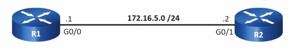
- R1 sends a hello packet as a multicast containing its router ID and is asking if there is anyone else on this link
- No hello packets received in this state
2. Init state
- R2 receives the hello packet from R1 and adds R1’s router id to its neighbor list.
- R2 then replies to R1 by sending a hello packet as a unicast containing its router id and its neighbor list.
- when R1 sees itself in the neighbor table for R2, we are going to transition to the two way state.
- R1 adds R2’s router id to its neighbor table.
3. Two-Way state
- Only on multiaccess links which are usually ethernet connections, the routers elect a Designated Router (DR) and Backup Designated Router (BDR).
- The router with the highest OSPF priority will become DR and router with second-highest priority will become BDR. If the priority of the routers are the same, then the router with the highest Router ID is selected as DR and the router with second-highest Router ID is selected as BDR.
- Routers usually have a default priority of 1
- In the diagram, since both have a default priority of 1, R2 will be the DR since it has a higher Router ID and R1 will be the BDR.
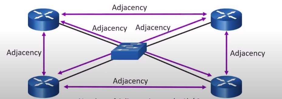
Multiaccess networks can create 2 challenges for OSPF:
- Creation of multiple adjacencies. Ethernet networks could interconnect many ospf routers over a common link which could lead to an excessive number of LSAs
- Extensive flooding of LSAs. Anytime there is a change in topology or when OSPF is initialized, LSAs are flooded
All the routers have a full state with the DR and BDR while the routers not elected as DR or BDR can have a two way state with each other meaning they wont notify each other of any changes, only the DR and BDR will notify them.
R1 can notify the DR and BDR about a change, then the DR and BDR notify all the other routers. the ones in two way state wont notify each other hence prevents flooding LSAs
4. Exstart state
- The routers choose whose gonna share their LSDB first.
- Usually, the router with the highest Router ID will send the DBD packet which is a summary of what is contained in their LSDB.
5. Exchange state
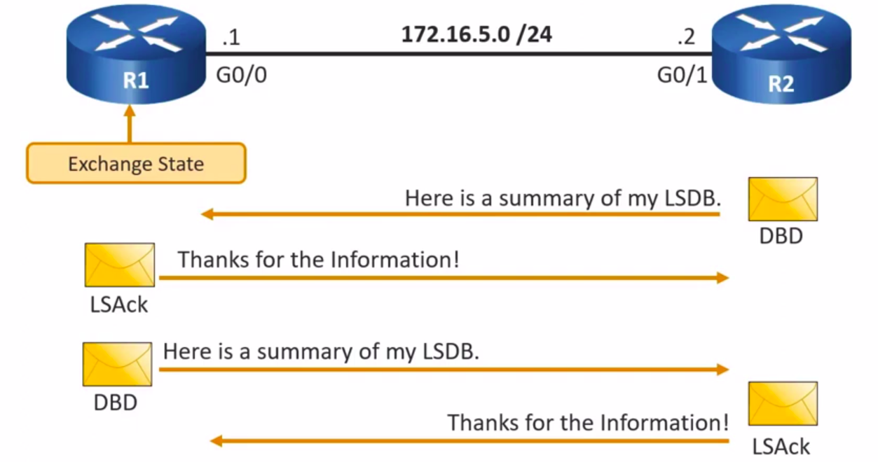
- In this step, routers exchange dbd packets.
- R2 sends the DBD packet since it has the highest Router ID.
- R1 sends an LSAck which acknowledges that it has received the DBD packet.
- R1 then sends its own DBD packet and R2 replies with an LSAck.
6. Loading state
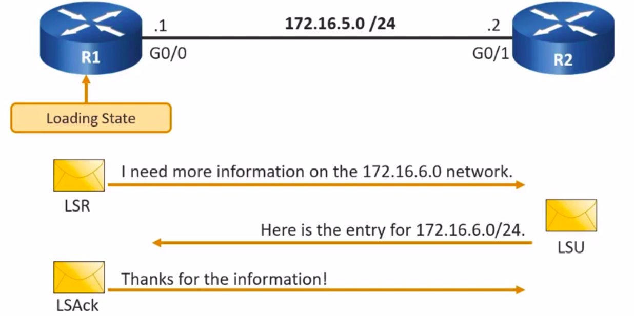
- Link State Requests (LSRs)and Link State Updates (LSUs) are used to gain additional route info.
- R1 compares the info from the DBD packet received with the info it has in its own LSDB.
- It can then request for more info of a particular entry like a subnet by sending an LSR.
- R2 then responds with an LSU which contains the info requested.
- R1 sends an LSAck.
- Routes are then processed using the SPF algorithm.
7. Full state
- Full convergence is reached since all the routers LSDB are fully synchronized.
MULTI AREA OSPF
Single area OSPF works great in small networks however as the networks grow, some down sides to single area OSPF start to surface:
- Huge LSDB. OSPF will gather the entire network info and create an LSDB. This database will be the same on every router on the entire network. This can become massively filled with info that the router doesn’t even really need.
- Massive routing tables. Huge routing tables will be generated on each router. This will contain every subnet within the entire network.
- Updates everywhere. OSPF is great at responding to changes, however in such a large network problem can occur. Every router will need to reevaluate all routes and run the SPF algorithm anytime a change occurs, even if that change is as small as a network cable being unplugged.
The solution! OSPF multi areas is designed to segments your network and allows routers to summarise routes between the areas reducing the problems mentioned.
- Each area should contain subnets that can be summarised.
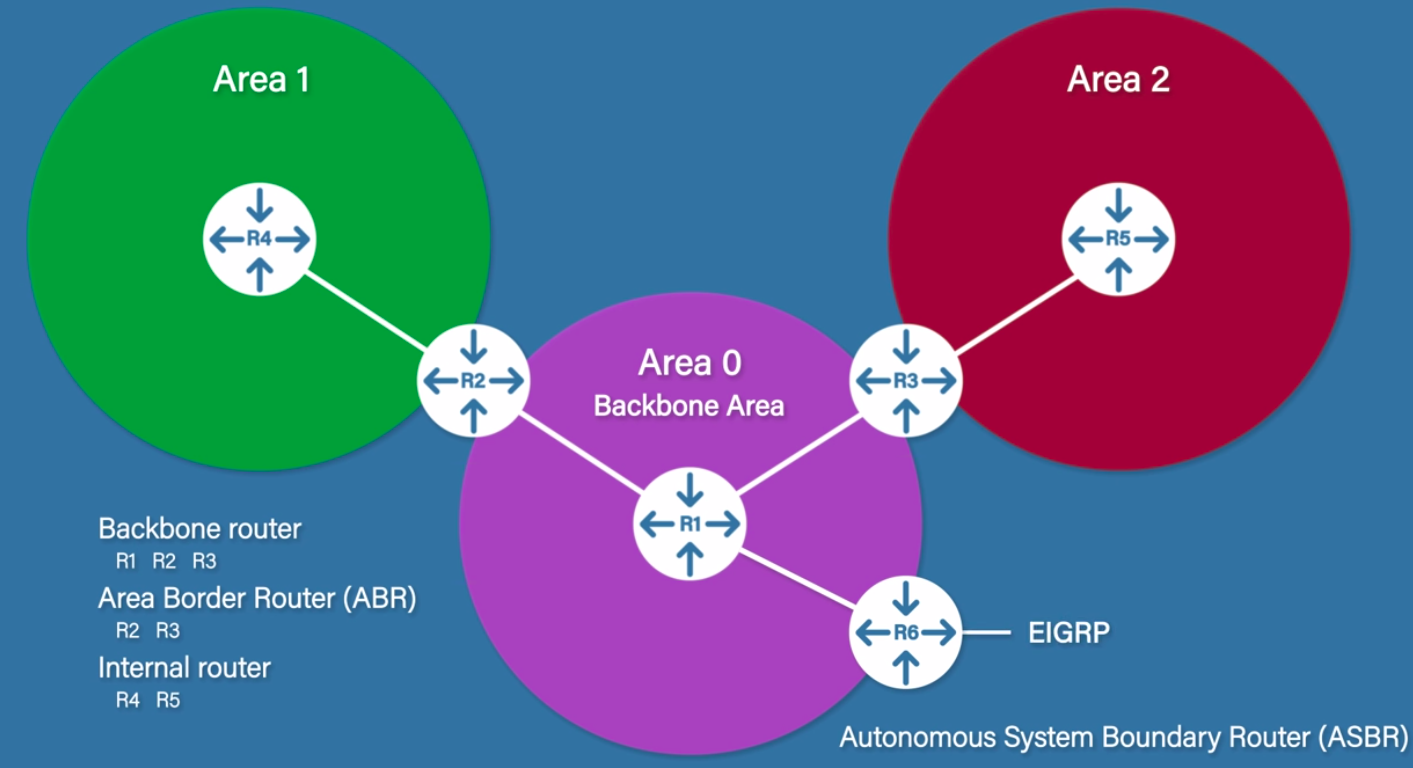
- All areas must connect to the Backbone Area/Area 0
Area border routers - Have interfaces in 2 or more areas and have the power to summarize routes from different areas and send a single route to Area 0. They will also summarize Area 0 networks and send a single route to the other areas.
When a change occurs in for example Area 2, R3 which is an ABR will deal with it by summarizing the networks again so there is no need for SPF algorithm to be run.
Backbone routers - routers in or partially in area 0 Internal routers - routers within a single area but not in the backbone area Autonomous System Boundary Router - are routers that are connected to other non-ospf routing protocols such as EIGRP
References
https://www.youtube.com/watch?v=kfvJ8QVJscc&t=668s
https://www.youtube.com/watch?v=PIMnj2oqYIo
https://www.youtube.com/watch?v=NblQUBWTzew